Default alignment based on the physical element geometry.
-
Align to Adjacent Level
Override default alignment if an adjacent level is found.
-
- Search Tolerance
Defines the search tolerance for the nearest level.
Length
Beams
Default
Default alignment based on the physical element geometry.
-
Align to Adjacent Level
Override alignment if an adjacent level is found.
-
- Search Tolerance
Defines the search tolerance for the nearest level.
Length
Align to Connected Floor
Override default alignment and level alignment if a connected floor is found.
-
1
Units according to Revit settings, to check or change go to Manage > Settings > Project Units
where you can also add a unit symbol for easier readability.
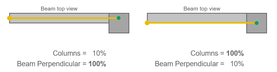
SOFiSTiK Analytical Model Generator minimizes the deviation of the analytical elements from their “optimal” position. The higher the priority, the lower the deviation.
SOFiSTiK Analytical Model Generator respects the adjustment limits when finding the optimal location for the analytical elements.
The limits are relative to the dimensions of the physical element (unless stated otherwise), measured from the center of the element.
Thus a limit results in the analytical element being placed within the physical element,
while a limit allows it to being placed outside.
Important
Adjustment limits prevail over element priorities.
This feature is only available for 2023-10 and above.
SOFiSTiK Analytical Model Generator respect these global settings according to the configuration file,
unless a local override is specified.
The following settings are available:
-
By default either Top/Center/Bottom of Element are used.
Option 1
The most adjacent level within a specified search tolerance is used.
Note
Only horizontal elements are aligned with adjacent floors.
Sloped beams and floors do not follow this setting, please specify a local override if needed.
Important
Only such levels with Analytical = True are considered during the search. To learn more, see Analytical Levels
Option 2
A connected floor is used.
This applies to analytical members for beams only.
Note
The later options supersede the former ones, e.g., a connected floor is more relevant than an adjacent level.
 results in the analytical element being placed within the physical element,
while a limit
results in the analytical element being placed within the physical element,
while a limit  allows it to being placed outside.