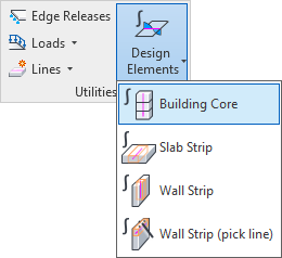
Design Elements > Building Core
Building Core places a specific Revit family in your project and associates it to selected structural walls. When analyzing a system, this family is interpreted as a Design Element by SOFiSTiK. Please refer to the Manual of module DECREATOR for more information about Design Elements.
Core Design Elements
Building cores are a specific Revit family of category Generic Model. They associate an oriented vertical axis to a selection of structural walls.
Along this axis, the Finite Element forces of the walls are integrated by SOFiSTiK.
These integrated forces can be displayed directly in Revit using Show Results or used as input for further design tasks in the ![]() SOFiSTiK Structural Desktop (SSD).
SOFiSTiK Structural Desktop (SSD).
Warning
Not all structural walls from the building core’s selection are equivalent.
Amongst the selection, the walls hosted in the lowest Revit level are considered Reference Walls. They define the general layout of the core and, if the corresponding property is active, determine its cross section.
The axis of the building core is generated at the center of gravity of the Reference Walls. It is vertical and covers the complete height of the wall selection. For the sake of simplification, openings in the walls do not influence the position of the axis. However, openings, when included in Revit’s analytical model, are accounted for in SOFiSTiK’s Finite Element models as well as in the forces calculated and integrated from it.
When walls from the selection are modified, the building core’s axis is not automatically updated. The user may manually account for the modification or delete the obsolete core to generate a new one.
Properties and Parameters
The SOFiSTiK Structural Properties panel allows to manage properties assigned to a building core instance.
Especially the user can:
adjust the building core’s name
highlight the walls associated to the core
edit the selection of walls associated to the core
active/deactivate the generation of a cross section for the core
Additionally, specific Revit shared parameters are assigned to building cores.
parameter
SOFiSTiK_Categorywill show the (read-only) value Design Elementparameter
SOFiSTiK_Typewill show the (read-only) value Building Coreparameter
SOFiSTiK_DesignElement_Namedisplays the core name as provided in the SOFiSTiK Structural Properties
These shared parameters can, for example, be added to schedules or used to define view filters.
Cross Sections
If the SOFiSTiK Structural Properties: Cross Section is active, a suitable cross section is generated and mapped to the building core.
This section is required to conduct a capacity check of the building core in the ![]() SOFiSTiK Structural Desktop (SSD).
SOFiSTiK Structural Desktop (SSD).
A building core cross section inherits the geometry, layout and properties of its Reference Walls. It has the same local coordinate system as the building core itself. The cross section can be visualized and adjusted in the Polygonal Section Dialog.
Reinforced concrete Reference Walls generate a reinforced concrete cross section for the building core. In this case, the cross section generated is automatically assigned a reinforcing steel.
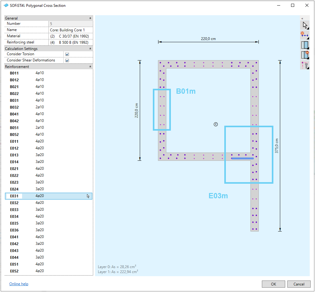
Typical cross section layout and reinforcement placements for a building core (click to enlarge)
Note
Automatically generated reinforcement placements for building cores are of the following two types:
Base reinforcement, labeled
B###, in Layer 0Placements in the center of each wall-part of the core, one placement on each side.
Edge reinforcements, labeled
E###, in Layer 1Placements at edges of each wall-part of the core, e.g., corners or free ends of the core geometry: two placements for each connected wall-part.
The three digit numbering scheme ### consists of two parts nnm with
nn |
increasing number for wall or edge |
m |
increasing number for reinforcement placements |
Results
When available in the SOFiSTiK *.cdb, Show Results displays analysis results for the building cores.
Therefore, it is possible to visualize in Revit forces and bending moments, integrated over all walls associated to the building core.
Working with Building Cores
To display integrated analysis results
The most simple use of Building Cores is the integration of forces from several walls along an axis. The following explanation describes how to achieve this step-by-step.
Modelling
Click on
Building Coreand select the walls for which you would like have integrated resultsValidate your selection by clicking on
FinishIn the dialog, assign a name to your building core
In the dialog, deactivate the option Set all walls belonging to this core as shear walls (it is not necessary for this workflow)
Validate the dialog with
OK, the building core family in loaded in the project and an instance is placed in the model
Analysis
Analyze a system from a view where the building core is visible. Automatically, results for the building core are generated in the SOFiSTiK
CDB
Evaluation of the results in Revit
In Revit, make sure to be in a view where the building core is visible
Click on
Show ResultsSelect as Data Source a system with the building core
Use the group Building Core of the side panel to access analysis results for the core
Together with SSD for advanced analyses and designs
Building Cores are at the centre of a seismic analysis and shear wall workflow together with the ![]() SOFiSTiK Structural Desktop (SSD).
This workflow is described exhaustively in our tutorial Seismic Analysis and Shear Design (BIM Workflow).
SOFiSTiK Structural Desktop (SSD).
This workflow is described exhaustively in our tutorial Seismic Analysis and Shear Design (BIM Workflow).
The following explanation provides a brief overview of the steps necessary for this workflow.
Modelling
Click on
Building Coreand select the walls which you would like to design as a coreValidate your selection by clicking on
FinishIn the dialog, assign a name to your building core
In the dialog, the option Set all walls belonging to this core as shear walls is necessary to conduct a Shear Design of the walls in SSD
Validate the dialog with
OK, the building core family in loaded in the project and an instance is placed in the modelAdditionally, all walls associated to the core now have their property
Design Elementset to Shear Wall
Analysis
Analyze a system from a view where the building core is visible. Automatically, Design Elements are generated in the SOFiSTiK
CDB.One main Design Element is generated for the building core itself
Each wall associated to the core is set as a Shear Wall. So for each, a member Design Element is also generated
Shear Walls design and Building Core capacity check in the
 SOFiSTiK Structural Desktop (SSD)
Open the
SOFiSTiK Structural Desktop (SSD) for the system where the building core was analyzedConduct a design of the core walls with the task Shear Wall Design (optional)
Perform a check of the core with the task Capacity Check for Building Cores
Evaluation of the results in Revit
After completing the designs in the
SOFiSTiK Structural Desktop (SSD) switch back to RevitMake sure to be in a view where the building core is visible
Click on
Show ResultsSelect as Data Source the system where you conducted the designs
Use the group Building Core of the side panel to access analysis results for the core
Hint
Each building core consists of a specific Design Element and the collection of the individual shear walls defining its cross section.
Secondary Groups for the elements involved are automatically created and available for post-processing in the ![]() SOFiSTiK Structural Desktop (SSD).
SOFiSTiK Structural Desktop (SSD).
Group ID |
Group Title |
Description |
|---|---|---|
‘CO##’ |
Name of Building Core(1) - Core |
Building Core Design Element as well as QUAD Finite Elements of associated walls |
‘CW##’ |
Name of Building Core(1) - Walls |
Shear wall Design Elements as well as QUAD Finite Elements of associated walls |
(1) Name of Building Core is the name defined during modelling (also name of corresponding cross section)
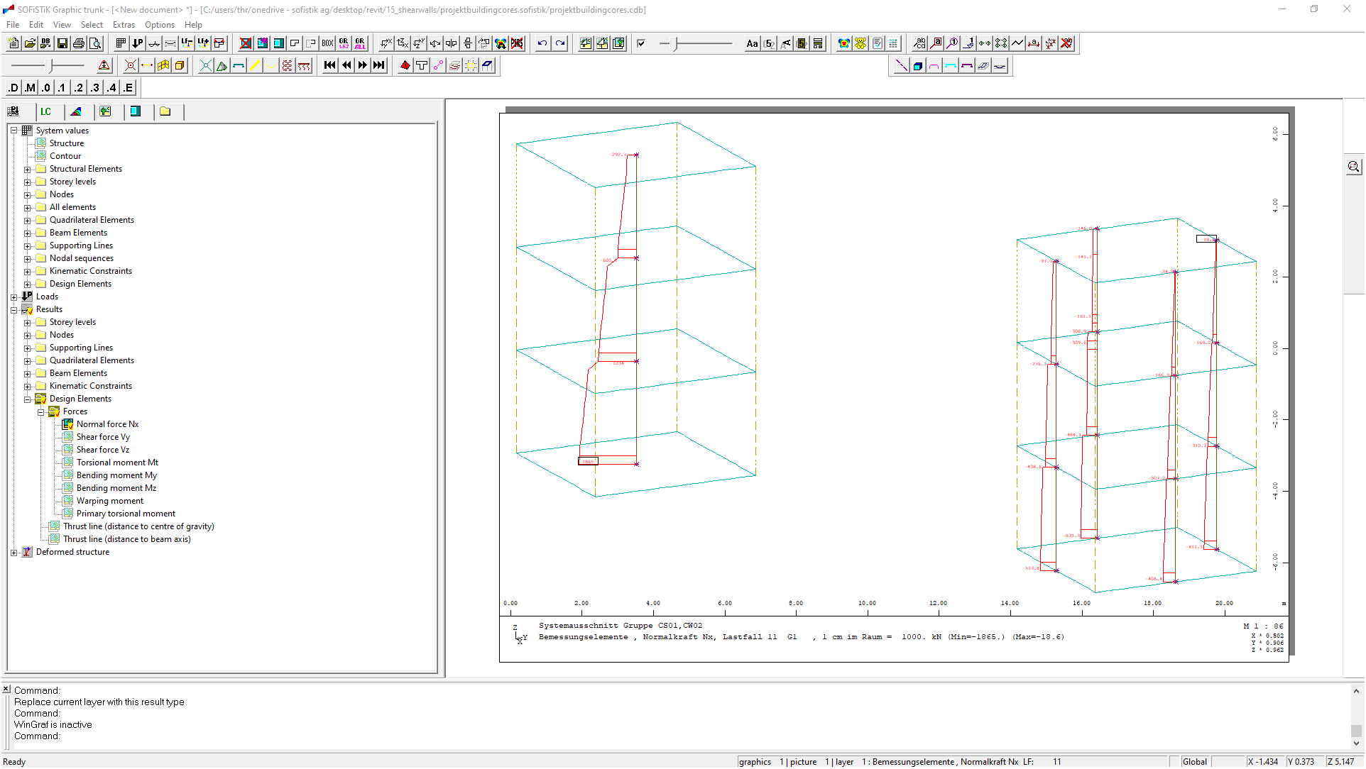
Graphic - Compare results for secondary groups CO and CW (click to enlarge)


